Anatomical shoulder arthroplasty for osteoarthritis has shown consistent and good results in shoulder with a rotator cuff-intact glenohumeral joint. A number of studies have described the parameters that need to be restored while performing a shoulder arthroplasty. Results depend on proper implant selection, positioning, and correct restoration of the glenohumeral parameters. Errors in treating the glenoid pathology, restoring the normal glenohumeral anatomy, and failure in achieving adequate soft-tissue balance are detrimental to the outcome. The present study reviews the normal glenohumeral parameters that need to be restored in an anatomical total shoulder arthroplasty and hemiarthroplasty. Furthermore, avoidable surgical errors while performing an anatomical shoulder arthroplasty are discussed.
Shoulder arthroplasty as an option for glenohumeral osteoarthritis, proximal humeral fractures, rheumatoid arthritis, and osteonecrosis has evolved since its first description by Jules Pean. In 1951 Charles Neer described a nonmodular vitallium prosthesis for the management of proximal humeral fractures, which was later used for the treatment of glenohumeral osteoarthritis.[1,2] Advances in the understanding of the biomechanics of the shoulder has led to emphasis on restoring the anatomical parameters of glenohumeral joint; a factor essential in maintaining the rotator cuff and the deltoid lever arm in the vertical plane and soft-tissue tension in the horizontal plane (Figure 1).[3]
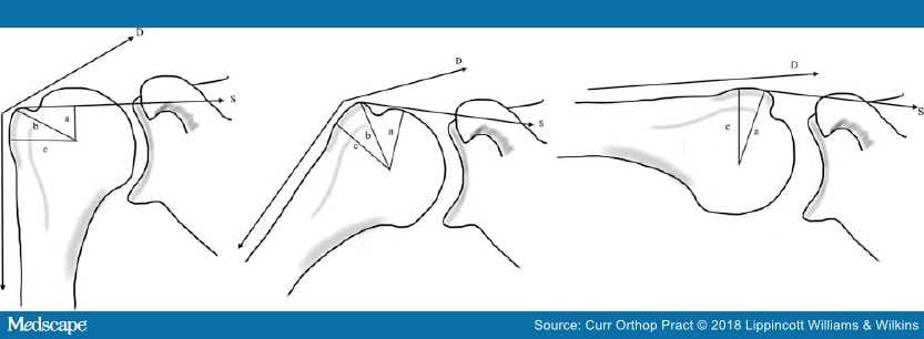
Figure 1.
Effect of humeral offset on the deltoid (D) and the supraspinatus (S) lever arm at various angles. "c" indicates the tuberosity offset'; "b" is the deltoid lever arm and "a" is the supraspinatus lever arm. With increasing abduction the lever arm becomes more dependent on the supraspinatus lever arm.3
Many studies have been done to assess various glenohumeral parameters in a different way and have varying degrees of errors with regard to their assessment of these parameters. In the subsequent sections, we review the described methods to map the anatomy of the glenohumeral joint and discuss the importance of restoring these parameters while performing an anatomic total shoulder arthroplasty (TSA) or a hemiarthroplasty (HA).
An understanding of the three-dimensional anatomy of the proximal humerus is essential for proper prosthetic design, placement, and positioning. The joint forces are determined by the extramedullary position of the prosthesis and the articular surface position by the intramedullary anatomy.[4] Changes of the prosthetic positioning relative to native anatomy may lead to altered glenohumeral kinematics and restriction of range of motion.[5,6] While performing an anatomical TSA the following parameters need to be considered:
Retroversion. The degree to which the proximal humeral articular surface is retroverted with respect to the shaft may be assessed preoperatively to prevent component malposition. The reference axis for measurement proximally has been defined in various studies by the articular surface plane, a line from the bicipital groove to the center of the articular surface, the line from greater tuberosity to the center of the articular surface, and distally by the transcondylar axis, the transtrochlear axis, or the forearm axis (Table 1).[5,7–13,15–21] The calculated angle of retroversion depends on the distal axis used for measurement and varies from 0 to 55 degrees in various studies (Table 1 and Figure 2).[4,8–13,15–20,22]
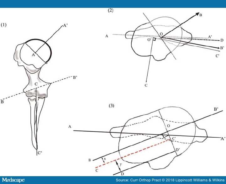
Figure 2.
Determination of the humeral head retroversion: (1) BB': the transepicondylar axis, AA': line drawn perpendicular to the articular plane passing through the center of the humeral head, CC': forearm axis. (2) Two dimensional analysis of the retroversion; AA': transepicondylar axis, OB: humeral head axis, CO': forearm axis and C'O' represents a perpendicular to the forearm axis. OD and OB' represent lines drawn parallel to AA' and O'C' intersecting the humeral head axis; angle BOD represents the angle of retroversion with reference to the epicondylar axis, BOB' represents the retroversion as measured with respect to the perpendicular forearm axis. (3) AA': transcondylar axis, BB': the humeral head axis, DD': a line through the bicipital groove drawn perpendicular to the articular plane.7,12,16,22–24
The intact bicipital groove serves as a landmark to assess humeral head retroversion.[21] The distance between the posterior edge of the bicipital groove and the central axis of the humeral head is relatively constant at 7.0 mm to 8.0 mm, representing an offset from the center of the groove by 30 degrees.[8,9,20] A significant degree of internal rotation (15.9 degrees) occurs along the course of the bicipital groove; a distal reference point along the bicipital groove may lead to excessive retroversion.[20] The site of insertion of the pectoralis major tendon is another landmark for referencing the retroversion of the proximal humerus, especially in patients with proximal humeral fractures when the anatomy of the bicipital groove is likely to be disrupted. The posterior fin of the prosthesis should be 10.6 mm posterior to the upper border of the pectoralis major and at an angle of about 24.6 degrees.[25,26]
Three-dimensional CT scan can reliably determine proximal humeral retroversion except where there is a distortion of the normal osseous anatomy; in such cases the opposite humerus may be used reliably as a template for determining the anatomical parameters.[27] In case of bilateral affliction with arthritic conditions, the osteophytes at the distal part of the humeral head may be used to determine the orientation of the articular surface plane.[12,13] The retroversion with respect to the transpicondylar axis is 17.1±8.1 degrees and 28.8±6.4 degrees when using the line perpendicular to the forearm axis as the distal reference (Figure 2).[12] Herningou et al.[12] suggested an inverse relation between the torsion of the proximal part of the humerus and the torsion of the distal part of the humerus (i.e. an increase in the retroversion led to a decrease in the carrying angle of the elbow at 90 degrees of flexion).[12] A factor that influences the intraoperative determination of retroversion while using the forearm axis as the guide.[12]
Version of the apex of the calcar fragment (metaversion) may be used to ascertain humeral head version in three- and four-part proximal humeral fractures where there is gross distortion of the anatomy (Figure 3). Metaversion differs from the humeral head version by about 1.8 degrees (range, 0.0–3.6 degrees).[17] The proximal part of the humeral metaphysis is more aligned with respect to the articular surface than the distal part; hence while using an uncemented prosthesis, incorrect neck osteotomy or use of long stems may lead to implant malposition.[28]
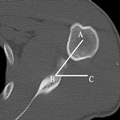
Figure 3.
Humeral metaversion: AB passes through the apex of metaphysis; BC is the horizontal. ABC is the angle of metaversion.
Humeral Head-shaft Angle and Humeral Head-inclination Angle. The inclination of the proximal humeral articular surface plane relative to the humeral shaft axis is known as the head-shaft angle and is measured between the humeral head axis drawn perpendicular to the articular surface plane and the humeral shaft axis. It has been found to vary between 120 and 145 degrees (Table 1 and Figure 4).[4,13,16,22] Prosthetic systems incorporate either a fixed inclination or a variable angle inclination for replacing the proximal humerus; for the prosthesis with the fixed angles, intramedullary devices help in ascertaining the orientation of the osteotomy cut. Variable angle devices, however, allow the surgeon to approximate the anatomy as closely as possible and replicate the normal glenohumeral kinetics.[6,29]
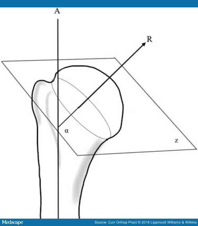
Figure 4.
Humeral inclination: α is the angle of inclination between the articular surface plane (z) and the humeral shaft axis (A).
Humeral Offset. It is defined as the displacement of the center of rotation of the humeral head from the orthopaedic axis (Figure 5).[4,13,16,22] The humeral head has a posterior offset of-2 to 10 mm and a medial offset of 4 to 14 mm (Table 1).[4,13,16,22] The medial offset is more important because the prosthesis must be designed and inserted in such a way so as to respect the medial-most components of the rotator cuff insertion (Figure 6).[16]Newer implants offer the surgeon the option of varying the offset compared to the first generation prosthesis thereby permitting restoration of the native anatomy. Correct alignment of the humeral axis to the implant axis restores the offset and center of rotation of the prosthetic joint (Figure 7).[23]
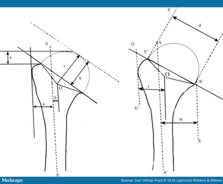
Figure 5.
AA' indicates the orthopaedic axis; (r) indicates the radius of curvature of the proximal humerus; (h) indicates the humeral head height; (x) indicates the tuberosity to head height; (a) width of the humeral canal; (b) indicates the offset; (t) indicates the tuberosity width; (m) indicates the effective humeral offset; (d) indicates the anatomic neck cut diameter; Y'OX' indicates the articular surface arc.16,19,23
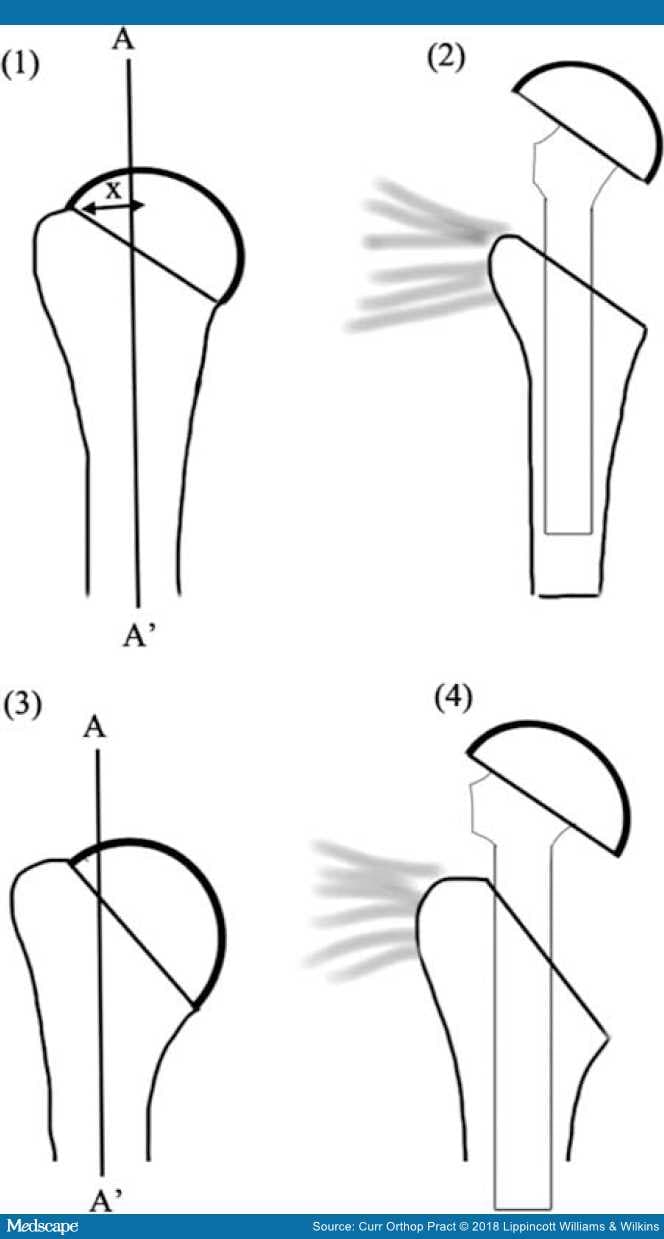
Figure 6.
Tuberosity offset variants and the effect of insertion of prosthesis with a fin: (i) high offset and (ii) no effect on the medial most cuff insertion with a finned prosthesis. (iii) low offset humerus with damage to the medial most cuff insertion with a finned implant . "P" represents the critical point and "X" represents the critical distance.16
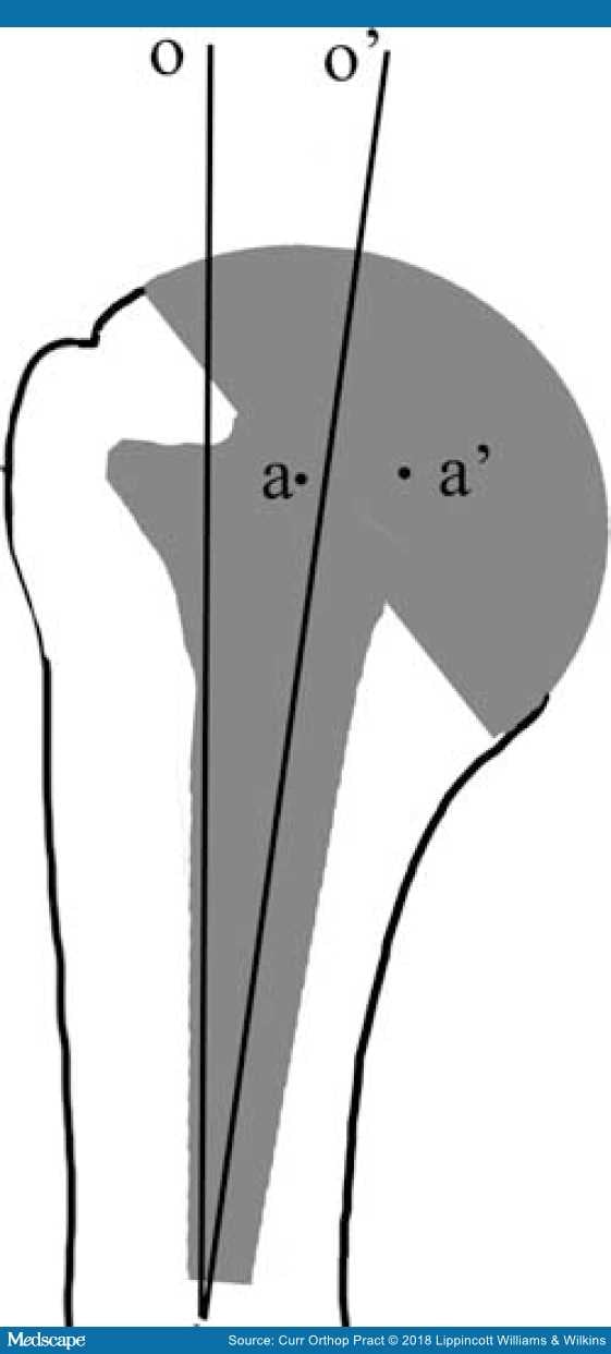
Figure 7.
Effect of offset mismatch (o v/s o') with a stem placed in varus leading to medialization of center of rotation (a v/s a').
Critical Line, Critical Point, and the Tuberosity Offset (Critical Distance). The critical line is defined as the most medial insertion line of the tendon of supraspinatus and is visible as a small step at the edge of the subchondral bone plate; the point where this line meets the humeral head equator is defined as the critical point. The shortest distance between the critical point and the axis of the humerus is defined as the critical distance. Based on the critical distance Hertel et al.[16] classified the offset into three variants: standard, high, and a low offset humerus. Straight-stemmed prostheses should be avoided in humeri with low offset because the stem may cause damage to the rotator cuff (Figure 6).[16]
Humeral Radius of Curvature, Head Height, and the Surface Arc (Figure 5) : The humeral head is not a perfect sphere, and there is a mismatch of about 12% in the frontal and the sagittal planes; the normal anatomic head has a radius of curvature of 20 to 30 mm with a head height that is 75% of the radius.[16] The head surface arc/articular surface arc is the angle between a line drawn from the lateral-most point of the articular surface, the center of the humeral head, and a line drawn from the inferior-most part of the articular surface to the center of the head (Figure 5).[23] This ranges from 130 to 150 degrees< in various studies (Table 1).
Head-to-greater-tuberosity Height. The head-to-greater-tuberosity height is the distance between the most superior point on the greater tuberosity and the most superior point of humeral head articular surface. It varies between 5 to 6 mm (Table 1 and Figure 5).
Humeral Canal Flare Index. The canal flare index is the ratio of the endosteal diameter at the neck of the humerus to the endosteal diameter 100 mm below (Figure 8). McPherson et al.,[30] in a cadaver study, analyzed the canal flare index and found that the humerus had a higher flare index in the coronal plane as compared to the sagittal plane.[30] As a consequence, an anatomical prosthesis needs to be asymmetrically shaped to achieve stability in rotation and bending.
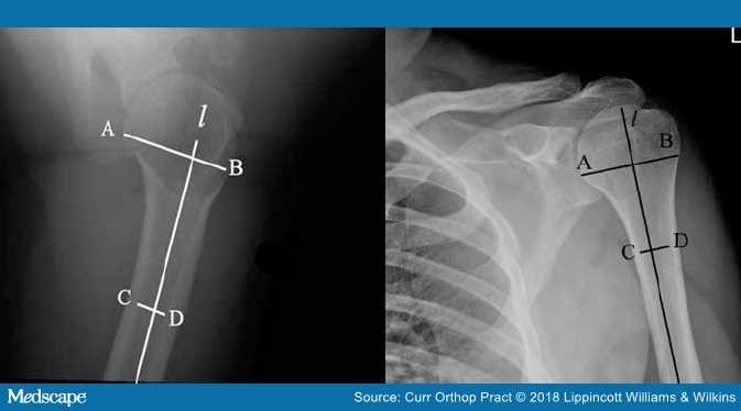
Figure 8.
Canal flare index: "l" is a line along the humeral shaft axis; AB is the endosteal diameter at the humeral neck and CD is the diameter 10 cm below the humeral neck.
Treating the glenoid is the most important determinant with regard to the outcome of a TSA, and many studies have been done in this regard. The orientation of the glenoid with respect to the scapular body plays an important role in shoulder biomechanics, the aberrations of which have been associated with cuff tears, glenohumeral arthritis, and poor outcomes in anatomic TSA.[31–33]
Glenoid Version and Axis. The normal glenoid has version ranging from 14 degrees retroversion to 12 degrees anteversion as described in various studies (Table 2). The glenoid has traditionally been assessed with radiographs and two-dimensional CT scans; however, patient positioning during the imaging may result in errors. Studies have demonstrated that for every 1 degree of abduction of the scapula, the apparent glenoid version changes by 0.42 degrees.[33,37,45–47] Inaccuracies in radiographs arise as (a) most of the conventional axillary radiographs are not true projections of the glenoid with a perfect overlap of the superior and inferior margin, (b) the image of the scapula on the radiograph depends on the orientation of the X-ray beam and (c) the medial scapular border is not seen on an axillary radiograph, which leads to the measurement of the glenoid neck-articular surface angle rather than the true glenoid version.[43] Friedman et al.[37] defined the glenoid version in two-dimensional CT scans as the angle between the line of neutral version (line orthogonal to a line connecting the medial angle of the scapula and the midpoint of the glenoid) and a line connecting the anterior and the posterior margins of the glenoid; if the posterior margin of the glenoid was posterior to the line of neutral version, the glenoid was set to be in retroversion (Figure 9). The authors found anteversion to be 2±5 degrees by this method. An alternate method was described by Randelli and Gambrioli[48] who defined glenoid version as the angle that is complementary to the one formed by the intersection of the scapular body axis and the glenoid surface (Figure 9). The Friedman method might be useful in the presence of a curved scapula and for all glenoid types irrespective of degenerative changes.[49] Poon et al.[49]suggested a two-dimensional CT scan method based on the endosteal triangle and not the glenoid face. At the midglenoid level, a line bisecting the medial angle of the endosteal triangle is the line of neutral version; the angle formed between the line of neutral version and a line parallel to the glenoid gives the angle of glenoid version. The glenoid version was found to be 19±3 degrees by this method.[49] The fulcrum axis (i.e. the line connecting the posterolateral corner of the acromion and tip of the coracoid) makes an angle of 1.8±4.5 degrees with the articular surface plane of the glenoid and can be used to determine preoperatively and postoperatively the amount of version.[39] Although the assessment of the glenoid version with two-dimensional CT is more accurate, it is still not error free. There is a twisting of the glenoid from the superior to the inferior direction, leading to a change in version and an error in the measurement of version with conventional two-dimensional CT scans.[42] Three-dimensional CT automation of the glenoid, though more expensive and not available at all centers, allows the analysis of the scapula as a free body, thereby eliminating the error from patient positioning. A better assessment of bone loss and glenoid version guides the intraoperative decision making.[34,38,41,42] Scalise et al.[38] described a glenoid vault model to estimate glenoid version in osteoarthritis; the vault was positioned in a best fit position for the scapula; the retroversion was calculated as the angle between a line drawn parallel to the face of the glenoid and a line along the lateral face of the positioned model (Figure 10).[38]
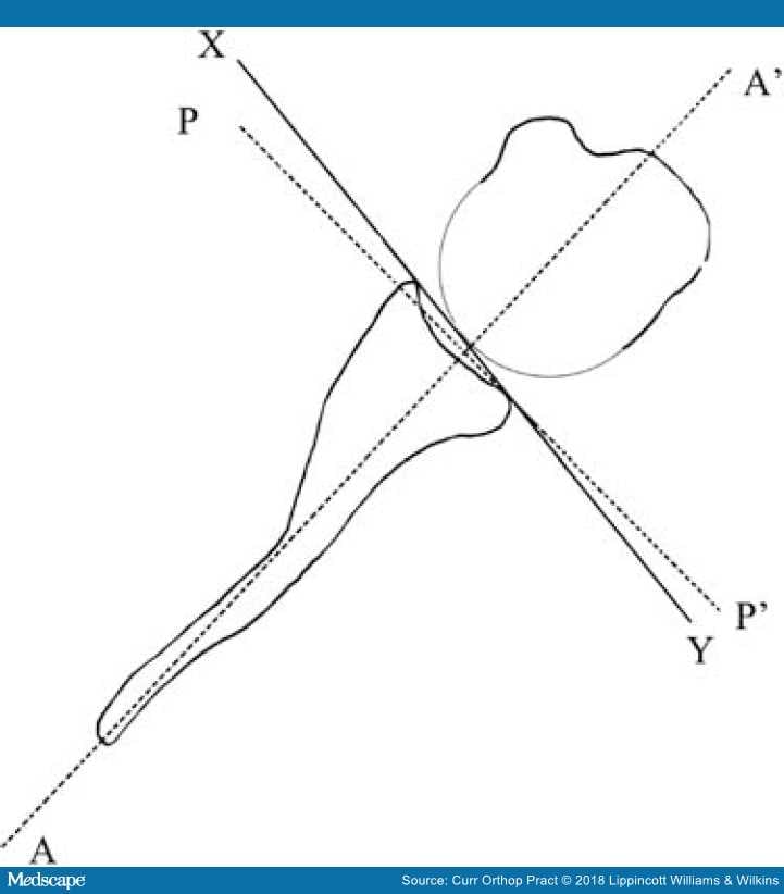
Figure 9.
Calculation of the glenoid version: AA': line drawn connecting the midpoint of the glenoid and the medial scapular angle; XY represents the glenoid axis; PP' is a line drawn perpendicular to AA' and is the line of neutral version. The angle between PP' and XY represents the glenoid version by Friedman method37 and the angle between AA' and XY represents the version as calculated by the Randelli48 method.
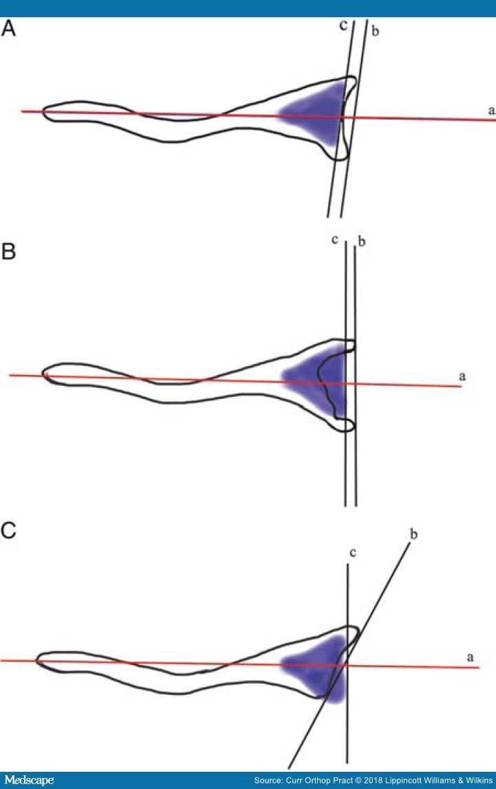
Figure 10.
The glenoid vault model: "c" represents a tangent to the vault model and "b" represents a line tangent to anterior and posterior margin of the glenoid; "a" represents the scapular axis. (A) Normal shoulder with equal retroversion of the vault and the glenoid. (B) Central glenoid wear with glenoid bone stock loss calculable from the vault model. (C) Posterior glenoid wear with normal vault retroversion different from the arthritic glenoid.
It has been suggested that in an arthritic glenoid, erosion rather than version leads to humeral head subluxation.[35,50] Walch et al.[50] described an index of subluxation, which is calculated as a percentage of the humeral head posterior to a line drawn through the mid-glenoid.[50] They described a classification for evaluation of the glenoid in glenohumeral osteoarthritis in which the glenoid was classified as type A (subtypes A1 and A2) with central glenoid erosion, type B with (subtypes B1 and B2) asymmetric posterior erosion, and a type C glenoid, which was a dysplastic glenoid with retroversion >25.[50]
Anterior Glenoid Vault Angle, Glenoid Axis (Figure 11): The anterior glenoid wall angle is defined as the angle between the anterior glenoid wall and the plane of the scapula.[40]The glenoid axis is defined as the tangent to the anterior and posterior edges of the glenoid, seen through a CT scan slice, passing through the center of the glenoid cavity.[14]
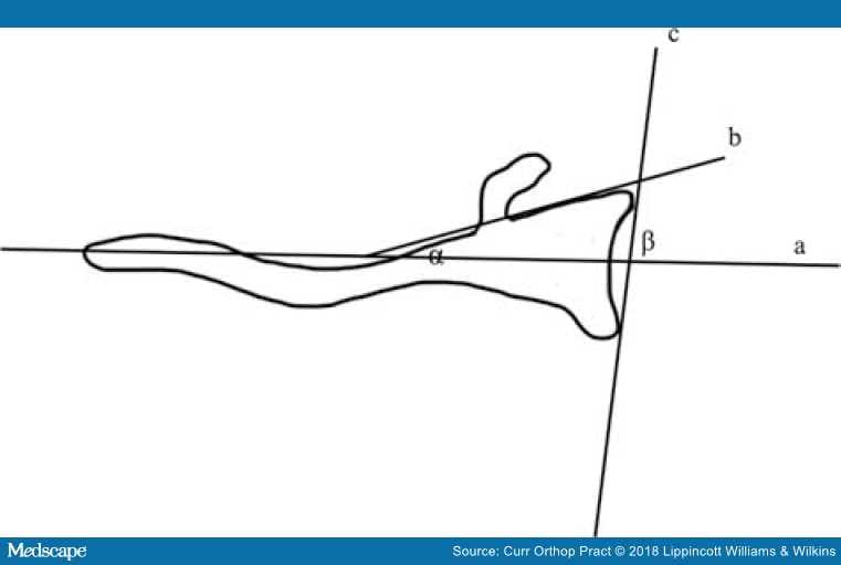
Figure 11.
The anterior glenoid vault angle α, between the scapular axis and the anterior glenoid wall; β, the glenoid axis between the scapular axis and a tangent to anterior and posterior glenoid rim.
Glenoid Inclination. The average inclination of the glenoid vault from cadaver studies has been reported to be 4 degrees (-7 to 15.8 degrees; Table 2). It can be measured in the frontal radiograph with the arm lying next to the side of the body by calculating the angle between a line joining the superior and the inferior glenoid rim and a line drawn through the lateral base of the coracoid process; a negative value represents an inferiorly directed glenoid while a superiorly directed glenoid shows a positive value (Figure 12).[44] Maurer et al.[51] described a new method of measurement of glenoid inclination on a standard radiograph and CT scans. They observed that assessment of the inclination by means of an angle between the floor of the supraspinatus fossa and the glenoid fossa was 74.5±7.5 degrees in radiographs and 75.9±5.5 degrees in CT scans; this method of measuring the inclination had the highest interobserver and intraobserver correlation and was least susceptible to variation in the radiographs and CT scans (Figure 13).[51]
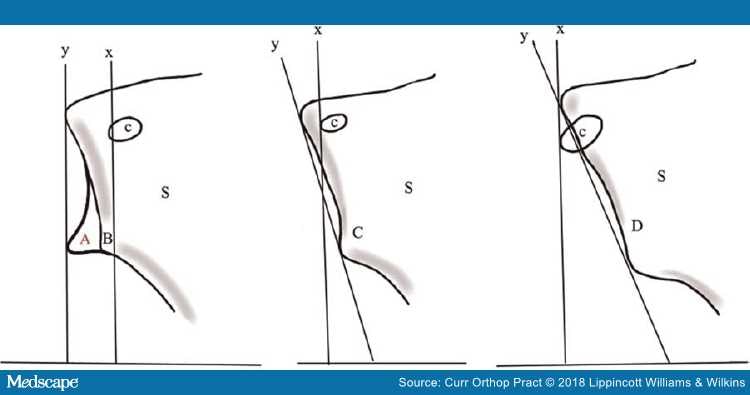
Figure 12.
Glenoid inclination abnormalities in glenohumeral osteoarthritis: x is a perpendicular line drawn through the base of the coracoid (c); "y" represents a line through the superior and the inferior edge of the glenoid normally; "x" should be parallel to "y"; A represents a normal glenoid, B,C,D represent abnormal glenoids. "S" represents the scapula.44
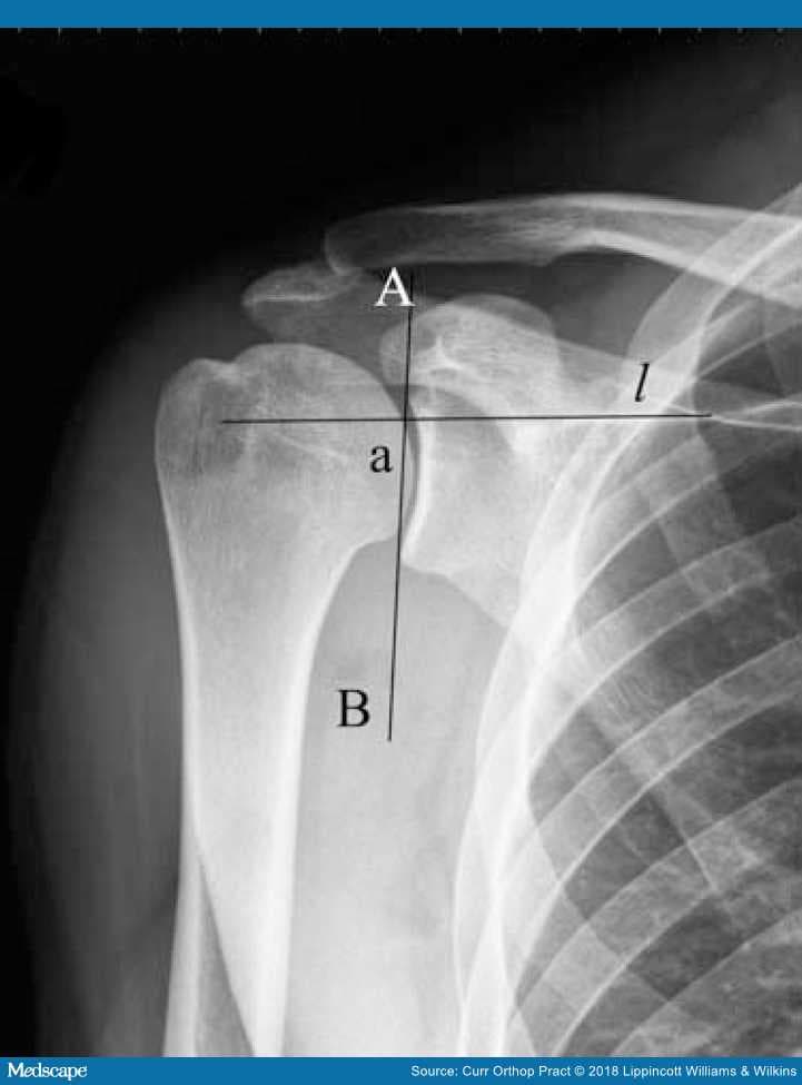
Figure 13.
The glenoid inclination: "a" between a line "l" along the supraspinatus fossa and AB as tangent to the superior and inferior glenoid rim.
Glenoid Height and Width. Glenoid height is defined as the distance between the most superior and the most inferior points on the glenoid. Various authors have reported the glenoid height to be between 37–40 mm (Table 2). Glenoid width is defined as the distance between the most anterior and the most posterior points on the glenoid and depends on the shape of the glenoid. A pear-shaped glenoid has a narrow superior aspect and broader inferior aspect compared to an elliptical or oval glenoid, which has a broader middle portion. The mean glenoid width in various studies has been reported to be 25–28 mm (Table 3).
Glenoid Endosteal Dimensions. The glenoid is larger in the coronal plane than the transverse plane, with the dimension being 41.0±6.1 mm in the coronal plane and 22.9±4.6 mm in the transverse plane; this has important implications in the prosthetic design because a glenoid implant with a rectangular keel in the coronal plane and a triangular keel in the transverse plane may provide better fixation in addition to more resistance to bending in either plane and have greater area of force distribution.[27]
Glenoid Bone Architecture. The glenoid bone architecture is critical for component fixation.[52] The glenoid has thick trabecular struts connecting the subchondral plate to the scapular spine, with peak volume at the posterior glenoid accounting for the better mechanical support.[53] The best quadrants of the glenoid for fixation are the anterior pillar formed by the coracoid base, the center of the glenoid, and at the posterior aspect of the glenoid as values of total bone volume (BV) and trabecular bone volume (TV), subchondral thickness, elastic modulus are highest in these regions.[34,53,54] The least values of BV/TV are observed at the anteroinferior quadrant of the glenoid (Figure 14).[53]
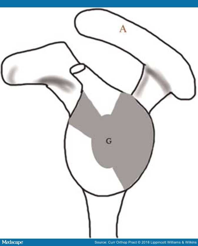
Figure 14.
En-face view of the glenoid demonstrating the distribution of bone density. The shaded regions represent areas of peak bone density and are suited for screw placement. "G" represents the glenoid and "A" represents the acromion.53
The glenohumeral joint is a ball-and-socket joint, consisting of an osseous nonconforming glenoid, which articulates with the humeral head; the cartilage and the labrum increase the conformity. The glenohumeral joint not only shows rotatory but translatory movements of the humeral head as well.[5] The parameters to be considered while analyzing the glenohumeral joint are as follows.
The Glenohumeral Center of Rotation. The geometric center of rotation of the glenohumeral joint has been defined as the center of a sphere fitted through the glenoid surface, with a radius approximating the humeral head. The kinematic center of rotation of the glenohumeral joint is on the other hand calculated through various functional or geometric methods and has been found to coincide with the geometric center of rotation of the glenohumeral joint under physiological conditions.[55,56] At extremes of motion the glenohumeral joint has accompanied translations and may not function like a true ball and socket joint.[57] An alteration in the glenohumeral joint center of rotation can affect the tuberosity position, rotator cuff tension, and capsular tension leading to altered glenohumeral kinematics and contact pressures.[58]
The Glenohumeral Conformity Index. The ratio of the radius of curvature of the humeral head to the radius of curvature of the glenoid cavity is known as the conformity index. The glenohumeral joint is a nonconforming joint with an index of 0.72 in the coronal plane and 0.63 in the sagittal plane.[30] The cartilage and the labrum make it a semiconforming joint.[59] A prosthesis with a conformity of 0.8–0.88 or a radial mismatch achieves translations similar to a natural joint.[60] Increase in the conformity can lead to increased forces at the glenoid component–cement interface and loosening.[61]
The Glenoid Constrained Index. This index describes the sector of a circle that the glenoid represents and is defined as the arc of enclosure of the glenoid cavity divided by 360. The normal glenoid cavity is unconstrained with a greater craniocaudal (index of 0.18 compared to 0.13 in sagittal) curvature, which assists in preventing the upward migration of the humeral head.[30]
Coracoid to Glenoid Articular Surface Distance, Acromion to Tuberosity Distance. The distance from the base of the coracoid process to the deepest point of the glenoid articular surface is 1.3±2.4 mm. The distance from the lateral aspect of the acromion to the lateral aspect of the greater tuberosity varies between 15–20 mm and correlates with the head size; both these parameters can be evaluated intraoperatively and soft-tissue tension determined.[19]
Glenohumeral Kinematics. Any glenohumeral motion results in coupled motion in three planes; elevation in a plane anterior to the scapula results in obligatory external rotation, and, conversely, elevation in a plane posterior to that of scapula results in obligatory internal rotation. The obligatory external rotation on elevation is necessary to clear the tuberosity from the acromial arch and to accommodate for the humeral head retroversion, thereby achieving optimal glenohumeral contact.[62] With an increase in the humeral abduction, there is an increase in the contact area of the glenoid with a resultant decrease of the joint pressure. Warner et al. observed that the glenoid contact area was centered over the bare area, where cartilage is thinner but with a thicker layer of subchondral bone.[63] Both during active as well as passive elevation, the humeral head translates anteriorly and inferiorly; the translations observed during active motion are less and more centered on the glenoid as compared to those during passive motion.[64]
Preoperative accurate assessment of the glenohumeral parameters is necessary for correct placement of the endoprosthesis with respect to the glenoid; malcentering of the humeral head leads to eccentric glenoid loading causing accelerated wear and instability.[65–67]
Despite the myriad ways to assess retroversion of the humeral head, the humeral head osteotomy is planned at 20–30 degrees intraoperatively with regards to the forearm axis.[68]
The humeral head retroversion becomes more important in the setting of a HA for proximal humeral fracture; excessive retroversion of more than 40 degrees, superior placement of more than 1 cm, and inferior placement of more than 1.5 cm is associated with a poor outcome and tuberosity nonunion. It is in such cases that the preoperative determination of the proximal humeral retroversion from the opposite extremity is important.[69] In the scenario of shoulder HA for proximal humerus in which the proximal part of the bicipital groove may be distorted, the distal part of the groove is a reliable landmark to assess the retroversion.[70] Johnson et al.[70] found a significant correlation between the rotation of the groove and humeral retroversion; the distal 15 mm of the groove and second half showed a correlation of 0.78 and 0.83, respectively. Additionally, the site of insertion of the pectoralis major tendon may be used as a landmark to assess the retroversion as described before and the humeral head height which is at 5.6 mm from the tendon insertion or 17.5% of the humeral length.[25]
Uncemented humeral stems achieve endosteal contact over a large surface area to allow for bony ingrowth and stabilization; these are ideal in circumstances when the center of rotation of the native glenohumeral joint and prosthetic glenohumeral joint coincide, otherwise issues of malpositioning of the humeral head arise. In a hemiarthroplasty the head diameter is primarily determined by the resected humeral head size, whereas in a TSA the head diameter is determined by the radius of curvature of the glenoid component. The effect of canal fitting humeral component on the kinematics is small, which is mainly determined by the head-neck length and soft-tissue releases.[28] Tightening of the capsule and restriction of the range of motion are observed with an oversized humeral head component; conversely use of a smaller prosthetic head may lead to decreased glenohumeral contact earlier in the range of motion, increased contact pressures and glenoid wear. Also the glenoid may not be able to constrain the humeral head sufficiently leading to instability.[22]
Failure to restore the correct head tuberosity height and medial/lateral offset may result in poor results; high osteotomy in the humeral cut leads to superior displacement of the glenohumeral center of rotation and overstuffing of the joint. Varus and inferior placement of the stem also can cause loss of movement by increasing the lateral humeral offset.[71]
Approximately 20% of the population has excess varus or valgus of the humeral head, and the use of implants with a fixed neck-shaft angle in such individuals by an anatomical cut may lead to a gap between the implant and the neck cut. In a scenario of excess of valgus, this may lead to joint overstuffing, whereas in instances of a varus cut, the implant positioning may lead to tuberosity prominence and impingement.[29] Implants with a variable neck-shaft angle are particularly useful in such conditions to restore the proximal humeral anatomy.[29]
Positioning a prosthetic head too far superiorly, increasing its thickness, or a larger than anatomic size may lead to restriction of range of motion and glenohumeral translation earlier in range of motion, increasing the tension in the supraspinatus tendon and pinching it between the head and the acromion.[3,22,28] On the other hand, smaller than anatomical heads may predispose to issues of point loading, altered glenohumeral translations, and tuberosity impingement.[3,22,28]
In the scenario of a TSA, the glenoid version assumes paramount importance; despite the number of three-dimensional CT scan methods described, two-dimensional CT scans are equally reliable. Additionally, three-dimensional glenoid automation technology is expensive and not readily available to all surgeons.[72] Rouleau et al.[72] also suggested that in a B2 glenoid the Friedman method gives a more accurate assessment of the retroversion. Budge et al.[36] observed that when three-dimensional CT scans were compared to two-dimensional CT scans to assess glenoid version, almost 50% of the glenoids showed a difference in retroversion value compared to three-dimensional CT scans by more than 5 degrees; however, the interobserver reliability and intraobserver reliability of both the modalities were excellent. They concluded that the differences in version observed between the two modalities represented an inherent difference in the imaging methods.[36] Hoenecke et al.,[73] however, stated that although two-dimensional CT scan is subject to error because of the plane of the glenoid at which measurement is taken and because of patient positioning, it could be minimized by using three-dimensional reconstruction to select the mid-glenoid plane to measure the glenoid version. With their method they decreased the measurement error to less than 1 degree in 91% of their patients.[73] Landau et al.[74] postulated that determining the glenoid component alignment based on the glenoid version does not account for the variable relationship of the glenoid vault to the scapular body and the musculature, suggesting that the angle between the glenoid plane and the scapular neck may not be as significant as thought.
Preoperative assessment of glenoid bone deficiencies is important in planning the intraoperative line of management. Osteoarthritic glenoids have a posteroinferior wear that can be corrected by eccentric reaming to 10 degrees; for greater derangements bone grafting is preferred.[24] A malpositioned prosthesis could lead to asymmetric distribution of stresses on the glenoid and early component loosening and failure.[67] An increase in anteversion leads to anterior translation of the humeral head and eccentric loading of the anterior part of the glenoid.[75] Excessive retroversion of the glenoid component, on the other hand, leads to a number of issues such as (1) increased shearing and micromotion at the bone cement interface, (2) the implant peak strain, (3) posterior glenoid loading, (4) slipping, and (5) decreased posterior wall height which contributes to posterior instability.[58,76,77] Glenoid retroversion more than 15 degrees is associated with osteolysis; ideally glenoid version should be restored to within 10 degrees of native glenoid, which may be difficult in arthritic glenoids.[76,77] As an alternative to eccentric reaming, augmented or stepped glenoid components have been introduced that preserve more bone stock compared to eccentric reaming.[78] Additionally augmented glenoids have lesser stress at the cement layer compared to a glenoid implanted with eccentric reaming which has a medialized center of rotation.[79] However, the long-term follow-up of the current generation augmented glenoid component is lacking. Superior malpositioning of the humeral head leads to displacement of the center of rotation, decrease in the lever arm of the abductors, and inferior capsule tightening, resulting in a loss of overhead abduction. Additionally, eccentric glenoid loading, early wear, and supraspinatus tendinopathy may observed.[5,22,80,81]
Maurer et al.[51] demonstrated that measurement of the glenoid inclination by measuring the angle between the supraspinatus fossa and the glenoid was a reproducible and reliable method in abnormal scapulae. A downward facing glenoid balances supraspinatus deficiency and reduces superior humeral head migration.[82] A larger size glenoid component has significant effect on the stability with maximum effect being on the superoinferior axis and the least being on the anteroposterior axis.[83] This, however, must be balanced against eccentric loading, increased micromotion at the cement bone interface and overstuffing of the joint.[83]
Exactly how the biomechanical axis across the glenohumeral joint is determined by muscle forces and their interaction with the glenoid articular surface is still not known and as Landau et al.[74] have suggested further studies are needed to assess this complex interaction.
Anatomical TSA offers reliable and consistent pain relief in glenohumeral arthritis. Current third generation prosthetic systems allow a more accurate restoration of the proximal humeral anatomy. Although the humeral head version is arbitrarily kept at 20 to 30 degrees during the surgery, preoperative assessment of glenoid version and wear is essential. Adequate soft-tissue tension plays an important role for the outcome in terms of the postoperative range of motion and avoiding instability.